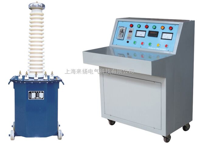
I. Overview In operation, the power system flows a very large current when an abnormal connection (ie, a short circuit) occurs between a phase and a phase or between a phase and a ground (or a neutral line). Its current value is much greater than the rated current and depends on the electrical distance from the short-circuit point to the power supply. For example, when a short circuit occurs at the generator end, the instantaneous value of the short-circuit current flowing through the generator can reach 10 to 15 times of the rated current . In large-capacity power systems, the short-circuit current can reach tens of thousands of amps. This will have serious consequences and consequences for the normal operation of the power system. Short-circuit impedance The so-called short-circuit impedance is the resistance formed by the short circuit of an electrical device, such as eddy current. In general, the short-circuit impedance of a transformer refers to the equivalent series impedance Zk = Rk + jXk between a pair of windings and a terminal of a winding at a rated frequency and a reference temperature . Since its value is calculated in addition to the calculation, it is also determined by the load test, so it is customarily referred to as the short-circuit voltage or impedance voltage. The short-circuit impedance of the transformer is simply the resistance and reactance of the two winding wires of the transformer. The actual value of the transformer short-circuit impedance is different for different capacities. The larger the capacity, the smaller the actual value of the short-circuit impedance. The short-circuit impedance of the transformer is directional. The values ​​from the primary side and from the secondary side are different, because of the conversion problem involving different impedance values. In the power system, the short-circuit impedance of the transformer is generally expressed in terms of the standard value, and the value of the standard value is the actual value / rated value. In this way, it is helpful to judge the load ratio of different capacity transformers. The short-circuit impedance test is the most direct method to identify whether the transformer is impacted by a short-circuit current or the transformer is impacted by mechanical forces during transportation and installation. It is of great significance to determine whether the transformer can be put into operation. It is also one of the basis for judging whether the transformer requires dismantling inspection. I. Overview of LYYD-200KV Test Transformer Product Is based on similar products YDJ (G) of the transformer, the transformer according to the national standard test ZBK41006 - 89 required by the improved production of a new product, the product has a small size, light weight, compact, functional, Easy to use and so on. It is used in power, industrial and mining, scientific research and other departments, and it is an indispensable instrument for high-voltage tests for power frequency withstand voltage test and DC leakage test of various high-voltage electrical equipment, electrical components, and insulation materials. Second, LYYD-200KV test transformer product structure Iron core is single frame type. The coil adopts the same core cylinder multi-layer tower structure. The primary low voltage winding is wound on the core and the secondary high voltage winding is wound on the outside of the low voltage winding. This coaxial arrangement reduces the coupling loss between the windings. The high-pressure silicon stack is encapsulated in a sleeve by a special process. The outer shell of the product is made into an octagonal structure with a good match with the core of the device, and the overall appearance is elegant and generous. Its internal and external structures are shown in Figure 1 . Product model meaning Y D Q C ( )-â–¡ / â–¡ Figure 1 : Schematic diagram Third, the working principle For single-phase transformers, bind group label II . The working process of a single transformer is connected to the power control box (Taiwan) with AC 220V ( 380K above 10KVA ) voltage, and the self-operated voltage regulator ( 50KVA above the regulator) is adjusted by the power control box (Taiwan). ~200V ( 10KVA and above 0~400V ) voltage is applied to the primary winding of the transformer. According to the principle of electromagnetic induction, the high voltage required by the test can be obtained in the high voltage winding of the transformer. Its working principle is shown in Figure 2 . 1 , the working principle of the schematic Fig. 2 : Schematic diagram of working principle Fig. 3 : Schematic diagram of three high-voltage test transformers Fourth, LYYD-200KV test transformer use and precautions 1 , the frequency of voltage test using the wiring method shown in Figure 5 . Before the power frequency withstand voltage test is performed, firstly select the resistance of the current limiting resistor ( water resistance ) according to the rated capacity of the transformer , and then adjust the ball spacing of the discharge ball gap according to the high voltage value to be added for the test object, in order to increase To measure the accuracy of the voltage applied to the test object, the FRC resistor and voltage divider should be connected to the high voltage side to measure the voltage. Fig. 4 : Schematic diagram of wiring principle for power frequency withstand voltage test Power frequency withstand test operation process precautions 1 , the test personnel should do a good job of responsibility division , set a good safety distance of the test site , carefully check the test object and test transformer grounding , and set up a special person to monitor security and observe the status of the work of the sample. 2 , to do DC voltage and leakage test using the wiring method shown in Figure 5 . Since it is an AC/DC dual-purpose transformer, the short-circuit bar of the high-voltage silicon stack should be pulled out of the casing so that the test transformer is in a DC output state. Before doing DC leakage test, according to the leakage current test, the output terminal breaking current does not exceed the maximum rectification of the high-voltage silicon stack, choose a good resistance of the current limiting resistor (water resistance), and then according to the requirements of the test object on the DC high voltage waveform Select the capacitor value of the high voltage filter capacitor. In order to improve the measurement accuracy of the voltage applied to the test object, an FRC resistor and voltage divider should be connected to the high voltage side to measure the voltage. Fig. 5 : Schematic diagram of wiring principle for DC leakage test Wiring schematic Wiring schematic When the start button is turned on, the red indicator light is on, indicating that the test transformer is connected to the control power supply and starts boosting. Precautions ( 1 ) The test personnel should do a good job in the division of responsibilities, set up the safety distance of the test site, carefully check the grounding of the test product and the test transformer, and provide special personnel to monitor the safety and observe the status of the tested product. Fifth, supporting the purchase of products The following products are for selection only, and need to be priced separately at the time of purchase. Sixth, the main test equipment selection 1 ã€Test transformer The test object capacitance Cx can be measured by the AC bridge. The commonly used test object capacity is selected according to Table 1 . The capacitance of several commonly used test items ( pF ) Table 1 2 , pressure regulating equipment Seven, test transformer technical instructions model capacity High voltage High voltage current Low voltage input Change ratio Temperature rise °C (KVA) (KV) (mA) Voltage (V) Current (A) Gao / Yi 30 minutes LYYD-1.5/50 1.5 50 30 200 7.5 500 10 LYYD-3/50 3 50 60 200 15 500 10 LYYD-5/50 5 50 100 200 25 500 10 LYYD-10/50 10 50 200 200 50 500 10 LYYD-15/50 15 50 300 200 75 500 10 LYYD-20/50 20 50 400 380 53 500 10 LYYD-30/50 30 50 600 380 79 500 10 LYYD-50/50 50 50 1,000 380 12 500 10 LYYD-5/100 5 100 50 200 25 1,000 10 LYYD-10/100 10 100 100 200 50 1,000 10 LYYD-20/100 20 100 200 400 50 1,000 10 LYYD-30/100 30 100 300 400 75 1,000 10 LYYD-50/100 50 100 500 400 125 1,000 10 LYYD-20/150 20 150 133 400 50 1500 10 LYYD-30/150 30 150 200 400 75 1500 10 LYYD-50/150 50 150 333 400 125 1500 10 LYYD-100/150 100 150 667 400 250 1500 10 LYYD-50/200 50 200 250 400 125 2000 10 LYYD-100/200 100 200 500 400 250 2000 10 LYYD-150/200 150 200 750 400 375 2000 10 LYYD-200/200 200 200 1,000 400 500 2000 10 LYYD-300/200 300 200 1500 400 600 2000 10 LYYD-50/300 50 300 170 400 125 3000 10 LYYD-100/300 100 300 333 400 250 3000 10 LYYD-150/300 150 300 500 400 375 3000 10 LYYD-200/300 200 300 667 400 500 3000 10 LYYD-300/300 300 300 3000 500 600 3000 10 1 , the use of environmental conditions Product Manual 1 Railway Sleeper,Railway Synitheric Sleeper,Railway Composite Sleepers,Composite Ties Railway Sleepers Anyang Railway Equipment CO.,Ltd , https://www.ayrailwayat.com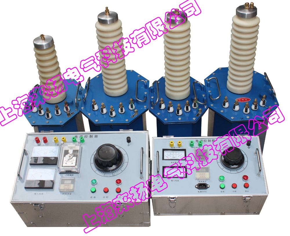
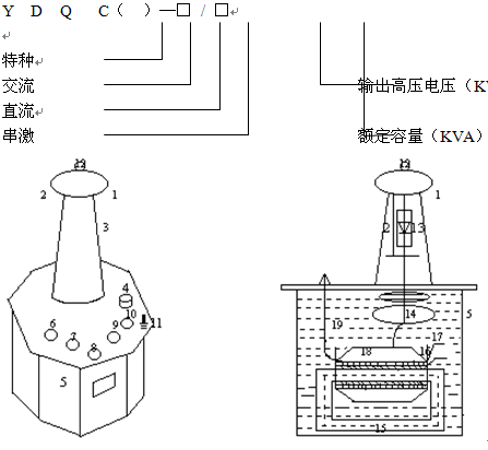
1- Equalizing ball; 2- Si stack shorting bar; 3- High pressure bushing; 4- Oil valve; 5- shell; 6 , 7- Adjustment of voltage input a , x terminal; 8 , 9- Instrument measurement E , F Terminals; 10- High - voltage tail X terminal; 11- Transformer housing ground terminal; 12- High voltage output A terminal; 13- High-voltage rectifier silicon stack; 14- Internal equalizing ring; 15-Transducer core; 16- Primary low voltage winding; - Measuring instrument windings; 18 - Secondary high voltage windings; 19 - Transformer oil. 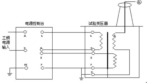
In the transformer: a and x are low-voltage input terminals; A and X are high-voltage output terminals; E and F are meter measuring terminals.
2. The working principle of a single AC-DC dual-phase transformer is shown in Figure 3 . As shown in the figure, high-voltage bushings contain a high-voltage silicon stack connected in series in the high-voltage loop for high-voltage rectification to obtain high DC voltage. When a high-voltage silicon stack is short-circuited by a short-circuit rod, an AC high voltage can be obtained, and the state thereof is an AC output. On the other hand, when a short-circuit rod is extracted, the state is a DC output.
3 , three transformers to get a higher voltage series theory shown in Figure 4 , the string-type transformer has great advantages, because the entire test device consists of a single series string test transformer, a single test transformer has a small size, It is light weight and easy to transport. It can be used in combination with a single test transformer output voltage several times in series, and can be used separately. The whole set of test equipment is small in investment and economical. Fig. 3 shows: In the series excitation of three series-excited series transformers , the output voltage of a single test transformer B1 , B2 , and B3 is U. The first and second test transformers have an excitation winding inside. For A1 , C1 and A2 , C2 . When the power supply voltage is applied to the control primary winding in the primary winding of the transformer B1 a1 of the first stage of the test, the x1, excitation winding A1, C1 B2 to give the primary winding of the supply transformer, the field winding of the transformer of the second stage A2 and B2, C2 and B3 to the test transformer . Due to the high-voltage tail of the first-stage transformer B1 and the case grounding, the second and third-level transformers B2 and B3 are insulated from the ground by insulation brackets, so that the output voltages of the transformers B1 , B2 , and B3 to the ground are 1 U , 2 U , and 3 U , respectively . . 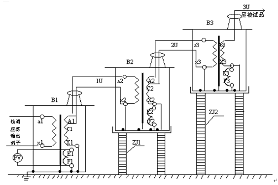
B1 , B2 , B3- series high voltage transformers; 1U , 2U , 3U- level voltage to ground;
PV- high voltage meter ( KV ); ZJ1 , ZJ2- insulated stand. 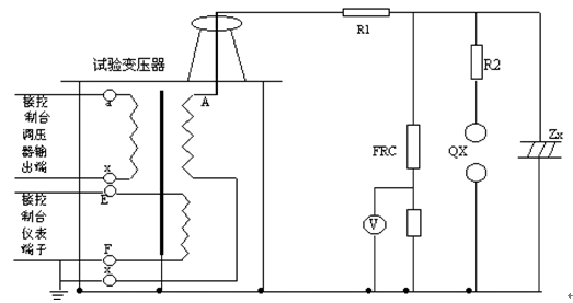
R1 , R2- current-limiting resistor; Qx- discharge ball gap; Zx- subject product;
FRC- resistance-capacitance voltage divider; V- divider high voltage meter.
In accordance with Figure 4 , combined with the power frequency withstand voltage test carried out in conjunction with Figure 2 connected to the working circuit, test the transformer's high-voltage winding X terminal (high voltage tail), instrumentation measurement winding of the F terminal, test transformer housing and power control box ( The cover) must be reliably grounded.
The primary winding X terminal of the transformer , the F terminal of the measuring winding of the instrument , and the X terminal (high voltage terminal) of the high voltage winding are all connected to the level test when three test transformers are used to make the power frequency withstand voltage test string. The outer shell of the transformer and the main body of the second and third test transformers must be placed on the insulating support. Except for the first stage, the main body of the second and third test transformers should not be grounded. The wiring is shown in Figure 3 .
Before connecting the power supply, the voltage regulator of the power control box (station) must be set to zero. After the power is turned on, the green indicator light is on, press the start button, the red indicator light is on, indicating that the test transformer has been connected to the control power supply and starts to boost.
From the zero position, rotate the regulator handwheel at a constant speed in the clockwise direction to boost the pressure. (Step-up methods are: rapid boost method, that is, 20S step-up step-up method, slow step-up step-up method, that is, 60S step-up step-up method, and very slow step-up step-up method to select) voltage is selected from zero. After the boosting speed has risen to 75% of your required rated test voltage, it will rise to your required test voltage at 2% of the rated test voltage per second , and pay close attention to the instructions of the measuring instrument and the condition of the tested product. The time for applying the voltage to the test sample comes later. The voltage regulator should be returned at a uniform speed within a few seconds. The high voltage is reduced to 1/3 or less of the test voltage. Press the stop button to stop the high voltage and low voltage output, and then cut off the power cable. The test is completed.
2. The main parts of the tested product should be cleaned and kept absolutely dry so as not to damage the test product and bring the error of the test value.
3. For the test of large-scale equipment, the airlift test of the test transformer should generally be conducted first, that is, when the test sample is not received, the voltage is boosted to the test voltage, so that the accuracy of the indication of the good instrument is calibrated, and the ball spacing of the discharge ball gap is adjusted.
4. When the pressure test is done, the boosting speed should not be too fast, and sudden pressure should be prevented. For example, the voltage regulator does not suddenly close at zero, nor can it suddenly lose power. Generally, it should be opened when the voltage regulator is reduced to zero. .
5. In the process of step-up or withstanding voltage test, if the following abnormalities are found, 1 the pointer of voltage and ammeter fluctuates greatly, 2 the sample product emits abnormal noise, 3 if the insulation is found to have charred or smoke, it shall be immediately Step down, cut off the power, stop the test and find out the reason.
6. When using this product for high voltage test, besides familiar with this manual, it must strictly implement the relevant national standards and operating procedures. 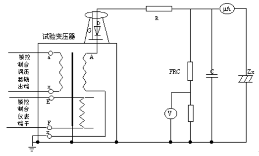
R- current - limiting resistor; C- high - voltage filter capacitor; Zx- tested product; G- silicon stack shorting bar;
FRC- resistance-capacity voltage divider; V- divider high voltage meter; uA- microampere meter; D- high voltage rectifier silicon stack.
According to Fig. 5 , the DC leakage test carried out in conjunction with Fig. 3 connects the working circuit. The X terminal (high voltage tail) of the high voltage winding of the test transformer, the F terminal of the instrument measuring winding , the housing of the test transformer and the casing of the power control box (station) must be reliably grounded. 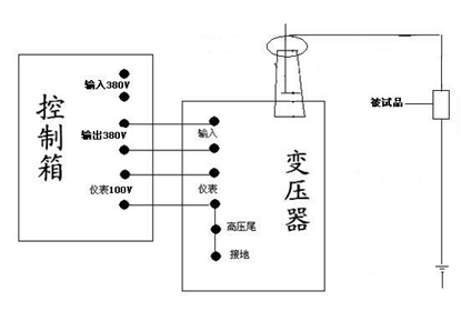
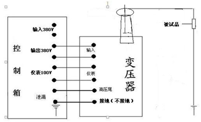
Before connecting the power supply, the voltage regulator of the power control box (station) must be set to zero. After the power is turned on, the green indicator light is on, press
From the zero position, rotate the regulator handwheel in a clockwise direction to boost the pressure. (Boost methods are: rapid boost method that is 20S step-by-step boost method; slow boost method, that is, 60S step-by-step boost method; step slow boost method for selection) voltage is selected from the start The pressure rate rises to the reference voltage you need for the rated test voltage or the rated DC current. The test should pay close attention to the direct current high voltage meter, leakage current meter indication and the condition of the tested product. After the test is completed, the high speed should be evenly reduced to zero. Press the stop button once, the high pressure and low pressure output will stop, and then cut off the power. At this time, the DC high-voltage discharge rod is used to fully discharge the test sample and the test apparatus itself.
( 2 ) Before testing the product to be tested, all external connections shall be removed and fully discharged. The main parts shall be cleaned and kept absolutely dry so as not to damage the test product and bring the error of the test value.
( 3 ) For large-capacity test items (capacitors, extra-long cables, etc.), the voltage should be raised slowly to prevent the test specimen from having a large charging current and burn out the microampere meter. If necessary, read the voltages separately by step pressure. The stable reading of the microampere meter.
( 4 ) During the test, the test object, microampere meter, and test device shall be closely monitored. Once flickering or breakdown occurs, the pressure shall be immediately reduced, the power shall be cut off, and the cause must be ascertained.
1.KZX series power supply control box capacity : 1KVA-5KVA , input voltage: 220V
2.KZT series power console capacity : 10KVA~300KVA input voltage: 220V or 380V
3. Digital microampere meter: SWB-II
4. High-voltage filter capacitor: 0.01MF , 40 ~ 100KV
5. High-voltage DC discharge bars: FBR — 70 , 140 , 210KV
6. Discharge ball gap: Q — 50 , 100 , 150 , 200 , 250 , 500
7. Standard test cup: 400ml
8. Folding cart: 150 , 300 type
9. Insulation bracket: 50 , 100 , 200 , 300 , 400KV
10. Resistor-capacitor divider: FRC — 50 , 100 , 150 , 200KV
11. High pressure silicon stack: 2DL — 150 , 300 , 450KV
12. Water resistance: 50, 100
The high voltage side rated voltage should not be less than the maximum test voltage of the test object, and the rated current should not be less than the maximum capacitance current of the tested product. The capacitive current of the test sample and the required capacity of the test transformer are calculated as: 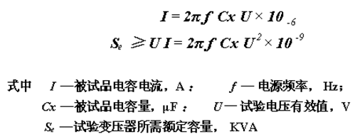

( 1 ) Self-operated regulator. The wide voltage regulation range, low power loss, and small waveform distortion are the best choices for this voltage regulation method. The capacity of the self-turning regulator is selected by the capacity of the test transformer of 0.75 to 1 times, which is suitable for the voltage regulation of the test transformer with a capacity of 100KVA or less.
( 2 ) Induction regulator. The pressure regulating range is large, the waveform distortion is small, but the structure is complicated and the price is expensive. When the capacity of the test transformer is large (for example, 100 KVA or more), it is used.
3 , current limiting resistor
The function of the current limiting resistor is to limit the breaking current when the test product is broken down, thereby protecting the test transformer and preventing the expansion of the fault. The value is based on the highest test voltage and is selected as 0.5 ~ 1 Ω / V (rms). The current limiting resistor can be water resistance. Note that water cannot fill the glass tube, leaving room to burst.
4 , discharge ball gap
Disposition of discharge ball gap is vertical and horizontal. The relationship between ball gap distance S and ball diameter D should be protected in the range of 0.05D ≤ S ≤ 0.5D . The resistance of water resistance on ball gap is generally 0.1 to 1 For Ω /V selection , the purpose of setting the discharge ball gap is to protect the important test object , and the overvoltage caused by misoperation or breakdown of the test object can be limited within the allowable range.
Ambient temperature is not higher than +40 °C, not lower than -20 °C; air relative humidity is not greater than 90% ; altitude is not more than 2000 meters;
2 , working voltage
The input voltage of the power control box (Taiwan) is 220V or 380V , and the relative error does not exceed ± 10% ; (The specific voltage is selected according to the user's test transformer specifications)
Eight, with the cargo file
Factory test report part 1
Product certification 1
Packing List 1 part
Transformer short-circuit impedance in electrical correct understanding
