Founded in 1994, Power Tech Mold Co., Ltd. main focus has been the manufacturing of plastics injection molding products. The purchase of a single and three multi-component injection molding machines and transformation into ODM (Original Design Manufacturer) has helped Power Tech cater to customers by designing, manufacturing, and producing a series of products. Power Tech has also established its mold and injection departments. By June 2007, the quality assurance department was established to monitor the whole manufacturing processes. This effectively enhances the quality of end projects and ensures clients’ right and satisfaction. (Source: Power Tech Mold Co., Ltd.) In this Armrest’s cup holder case, there is a huge difference existing between cup holder area and the main thickness of the cup. When the melt fills the mold, it creates a visible air-trap phenomenon. Leverage on CAE analysis to find out the optimum gate position to balance the melt flow and further optimize the thickness to prevent air trap problem. Engineers are able to successfully eliminate molding defects by utilizing preventive measures based on CAE analysis results. Quality improvement and production cost reduction have become crucial for customers in various industries. As a result, it becomes necessary for industries, while doing production planning, to have a solid mechanism of mold filling analysis before design and production stages. In the plastic industry, Moldex3D provides Power Tech a valuable guidance to break free from traditional methods and perspectives of manufacturing processing and planning. In this article, using Armrest’s cup holder as an example, after the cup holder is put through a carefully analysis by CAE several times, we can detect the difference that the change of each parameter makes. These differences enable the designer to review and prevent errors before production. This will allow the user to enhance competitiveness through significant reduction of cost and time. This case study involves an Armrest with the situation stated above (Fig. 1). There is a huge difference existing between cup holder area and main thickness of the cup (Fig. 2), and when the melt fills the mold it creates a visible air-trap phenomenon. Under the circumstance that the alteration of product shape is not allowed, aside from changing the thickness of the item, a simple solution does not seem to exist. Foregoing analysis and attempting a trial and error method to fix the problem would result in a prolonged process and incur much unnecessary expenses. The best course of action for Power Tech at this point would be to put it through a CAE analysis to discover the optimum gate position to balance the melt flow and further change the thickness to prevent the air-trap appearing in the first trial. Figure 3~5 show the progress of the melt flow. These figures show the upper part of the plastic flow is faster than the lower part. The problem is that when the upper part of the mold is filled, the lower part is barely completed thus the air-trap and the weld line problems occur. As the melt flows through the mold towards A, it fills B towards the lower recesses of the cup frame. The figures below show the progress at 83% and 91% completion. In terms of flow conditions, the flow speed on the bottom is relatively slow compared to the speed of the upper part of the cup; therefore, changing the thickness would be the key factor to avoid air-trap under the premise that the end product appearance would be changed as well. In this article, we chose thickening the bottom of the cup to let the plastic flow faster as the simulating scenario. Figure 6 demonstrates the changing of thickness. The red region in Figure 6 illustrates the mold with a thickness of 3mm. Some region’s thickness has been reduced to a thickness of 2.5mm to solve the problem of air-trap. Above figures show the simulation results are quite similar to actual short shot samples (Fig. 7~14). Moreover, the analysis results show that a weld-line occurs at the location of original air-trap because of the thickness change, which is the same as the actual short shot sample. Based on above analysis, when an end-product needs to change the flow condition or solve key problems, very often a company will adopt the method of thinning the major thickness. As the example in this article shows, although the air-trap problem may be solved due to the changing of major thickness, another problem to the end product might occur because the thickness of the cup remains the same. Therefore, under the premise that the appearance is to be unchanged, another way to change the direction and speed of the flow would be thickening some portions of the thickness. Before the test shot from design, mold producing to analysis, this time, some preventive measures have been planned out based on CAE analysis results so that engineers are able to successfully minimize the molding problems. Halloween Tote Bags,Pumpkin Tote Bag,Personalized Halloween Totes,Canvas Halloween Tote,Custom Halloween Tote Bags Sichuan Dole Bonz Trading Co., Ltd. , https://www.dlbzbag.com
![]()
Challenge
Solution
Benefits
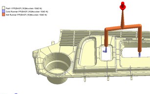
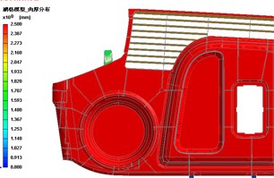
Fig. 1Â Â Armrest Model Geometry
Fig. 2Â Original Thickness Distribution
Actual sample correspond with Moldex3D predictions
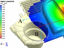
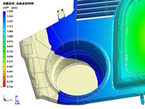
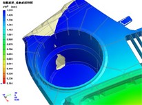
Fig. 3Â Melt front prediction at83%
filling stage
Fig. 4Â Â Melt front predictionat 91%
filling stage
Fig. 5Â Melt front predictionat 96.8% filling stage
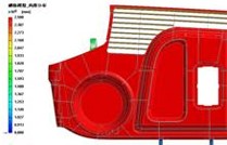
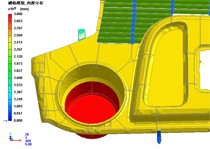
Fig. 6  (a)They yellow region’s thickness is reduced from 3mm to 2.5mm
Fig. 6 Â (b)
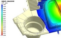
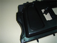
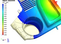
Fig. 7 Â Melt front prediction at 75% filling stage
Fig. 8 Â Actual short shot sample
Fig.9 Melt front prediction at 90% filling stageÂ
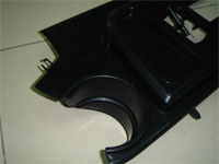
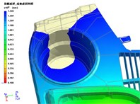
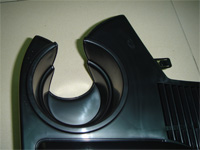
Fig.10 Actual short shot sample
Fig.11 Melt front prediction at 92% filling stage
Fig.12 Actual short shot sample
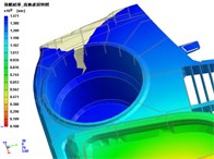
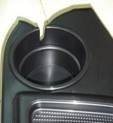
Â
Fig. 13 Â Melt front prediction at 96%
Fig. 14 Â Actual short shot filling stage sample
Â
Better accuracy, more trusts
Power Tech Uses Moldex3D to Solve Air Trap and Weld Line Problems
Customer Profile
